Introduction
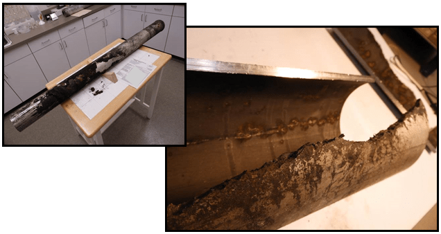
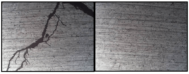
A section of TP 304 stainless steel pipe used in a high pressure steam condensate return system experienced stress corrosion cracking. This pipe was installed outdoors, underground, beneath a sidewalk along a roadway. Interestingly, the cracking occurred near the welded ends, while the main body of the pipe remained intact. Understanding why this happened is crucial for stopping future failures.
Background
First, our client explained that the system’s pipes arrived with factory installed insulating jackets. However, they left a 1ft section at each end exposed for welding during installation. Then, after finishing the welding, technicians added additional insulating jackets in the field to protect the joints. This design choice seemed practical, but it may have introduced issues that were not seen.

Observation and Analysis
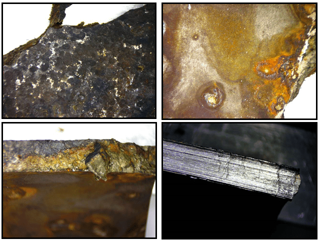
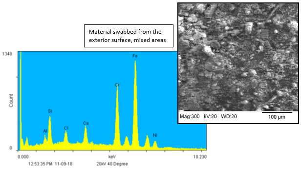
When we looked at the pipe sample, we noticed that the cracks were located at the seam between the factory installed and field installed jackets. This finding suggests that the seam likely added to the failure. It seems that the transition between these two insulating jackets created a weak point, leading to stress corrosion cracking under the operating conditions.

Conclusion
In conclusion, the location and appearance of the cracks indicate that the seam between the factory installed and field installed jackets played a significant role in the failure. By finding this issue, we can recommend improvements in installation procedures and materials to prevent future failures.
Additionally, understanding how these seams affect the integrity of the pipe will help us develop better solutions.


Contact Us
If you want more information about stress corrosion cracking or want to discuss how we can help with your material evaluation needs, please contact us at Anderson Materials Evaluation. Our team of experts is ready to provide insights and solutions tailored to your specific requirements.
