
Understanding Fracture Analysis
Fracture analysis is essential in finding the root causes of mechanical failures. When materials break, it can be sudden or due to prolonged cracking. Our analysis services help you understand the reasons behind these failures and how to prevent them in the future.
Our Fracture Analysis Capabilities
- Fractography: We study fracture surfaces to identify crack initiation and propagation. This includes looking at both macroscopic (visual) and microscopic (SEM) features.
- Material Types: We analyze fractures in metals, polymers, ceramics, glasses, and more.
- Detailed Reporting: Our reports provide detailed insights into the fracture mechanisms, modes, and material characteristics.
Examples of Our Fracture Analysis Services
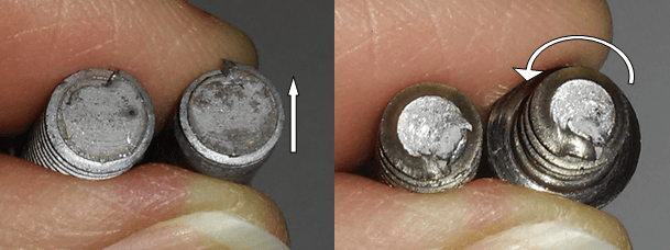
- Threaded Metal Fasteners (figure 1):
- Fatigue Cracking: Identifying cracks that form over time due to cyclic stress.
- Mechanical Overload: Understanding rapid fractures caused by excessive force.
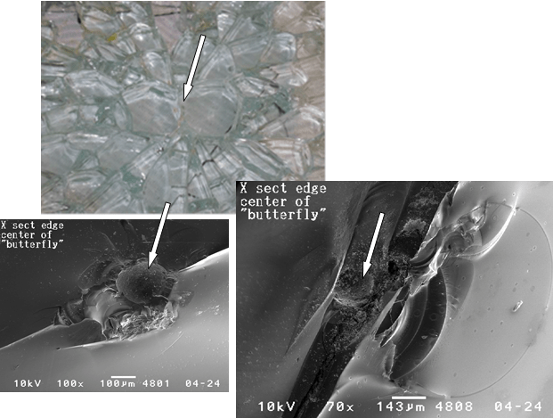
- Tempered Plate Glass (figure 2):
- Nickel Sulfide Inclusions: Analyzing breaks caused by internal inclusions leading to sudden failure.
- Natural Ruby Fractures:
- Cleavage Analysis: Examining brittle fractures in hard materials like rubies.
- Stainless Steel Tools:
- Ductile and Brittle Zones: Identifying zones of ductile and brittle fracture.
- Polycarbonate Materials:
- Environmental Stress Cracking: Analyzing cracks caused by chemical exposure and internal stress.
- Stainless Steel Wires:
- Ductile and Brittle Fractures: Understanding failure in reinforcement applications.
Why Choose Our Services?
- Expertise: Our team has extensive experience in testing various materials and fracture types.
- Comprehensive Analysis: We provide both qualitative and quantitative insights into the failure mechanisms.
- Preventative Solutions: Our analysis helps you prevent future failures and make informed decisions.
Get More Information
For more detailed information about our fracture analysis services, visit our detailed page. If you have specific needs or questions, contact us directly to discuss how we can assist with your fracture analysis requirements.